Infiniti QX60 Manual Key Start: A Comprehensive Guide (Updated 03/05/2026)
Modern vehicles, like the Infiniti QX60, utilize key fobs for convenience, but understanding the manual key start procedure is crucial for emergencies or fob malfunctions.
Understanding the QX60 Key System
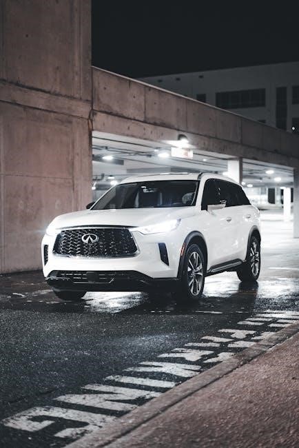
The Infiniti QX60’s key system represents a significant evolution from traditional vehicle access and ignition. Gone are the days when a simple metal key was all that was needed to operate a vehicle. Today’s QX60 employs a sophisticated system centered around a key fob, incorporating remote locking/unlocking, panic alarms, and, crucially, a transponder chip for security. This chip communicates with the vehicle’s immobilizer, preventing theft.
However, the QX60 doesn’t entirely abandon the concept of a physical key. Integrated within the key fob is a traditional, mechanical key. This manual key serves as a vital backup, offering a method to access and potentially start the vehicle when the key fob’s electronic functions are compromised – due to a dead battery, damage, or malfunction. Understanding how this system works, and the interplay between the fob and the manual key, is paramount for every QX60 owner.
The system is designed with layers of security, but also with user accessibility in mind. Knowing the limitations and capabilities of both the fob and the manual key ensures you’re prepared for various scenarios, maintaining control and peace of mind.
Key Fob Features & Functions
The Infiniti QX60 key fob is far more than a simple remote. It’s a central hub for controlling various vehicle functions, enhancing convenience and security. Primary functions include remote door locking and unlocking, allowing access without physically using the key. A panic button triggers the alarm and illuminates hazard lights, useful in emergency situations.
Beyond basic access, the fob often incorporates remote start capabilities (depending on trim level), enabling pre-conditioning of the cabin temperature. Many fobs also control the liftgate, adding to the convenience of loading and unloading. Crucially, the fob houses the transponder chip, essential for communicating with the vehicle’s immobilizer system and allowing the engine to start.
However, the fob’s reliance on battery power is a key consideration. A depleted battery renders the remote functions useless, necessitating the use of the integrated manual key. Understanding all fob functions, and recognizing the limitations imposed by battery life, is vital for QX60 owners.
Manual Key Operation: When and Why
The Infiniti QX60’s manual key operation serves as a vital backup when the key fob malfunctions or its battery is depleted. Relying solely on the fob can leave you stranded, making familiarity with the manual key essential. Situations demanding manual operation include a dead fob battery, fob damage preventing signal transmission, or interference disrupting the fob’s communication with the vehicle.
While modern vehicles prioritize fob-based convenience, the manual key ensures continued access and starting capability. It’s a crucial failsafe, particularly in remote locations or emergencies where immediate access is needed. Understanding the manual operation isn’t about replacing the fob; it’s about having a reliable alternative when technology fails.
Furthermore, certain security system interactions require manual key usage, as detailed later in this guide. Knowing when and why to utilize the manual key empowers QX60 owners with self-reliance and peace of mind, preventing potential disruptions to their journey.
Locating the Manual Key
The manual key for your Infiniti QX60 isn’t a separate entity; it’s ingeniously integrated within the key fob itself. This design prioritizes convenience and prevents the loss of a standalone key. To locate it, carefully examine your key fob. You’ll notice a small release button or latch, typically located on the side or end of the fob.
Pressing and holding this release button will initiate a sliding mechanism, revealing the physical key blade. The key blade is usually metallic and resembles a traditional car key. It’s important to note that the release mechanism might require a firm, deliberate press – avoid excessive force.
Once released, the manual key can be withdrawn from the fob. Familiarize yourself with this process before an emergency arises. Knowing precisely where the release button is and how to operate it will save valuable time and frustration when you need access to your QX60 without a functioning fob.
Accessing the Manual Key from the Fob
Retrieving the manual key from your Infiniti QX60’s key fob is a straightforward process, though it requires a bit of finesse. Locate the small, often recessed, release button on the fob’s body – typically found on the side or end. This button is specifically designed to unlock the key’s housing.
Press and hold the release button firmly. You should feel a slight click or resistance as the mechanism disengages. While holding the button, gently pull the key blade outwards. It will slide out from the fob’s casing. Avoid applying excessive force; if it doesn’t slide easily, ensure the release button is fully depressed.
Once fully extended, the manual key is ready for use. Remember to retract the key and securely close the housing after each use to protect the key blade and maintain the fob’s integrity. Practice this process a few times to become comfortable with it, ensuring quick access when needed.
Using the Manual Key to Unlock the Door
When your key fob isn’t responding, the manual key provides a reliable way to access your Infiniti QX60. Locate the driver’s side door keyhole – it’s typically concealed behind a small, removable cover. Gently pry this cover open to reveal the keyhole.
Insert the manual key blade fully into the keyhole. Apply gentle pressure and turn the key clockwise to unlock the door. You should hear the familiar unlocking sound of the central locking system engaging. If the door doesn’t unlock immediately, try wiggling the key slightly while turning it.
Once unlocked, the door can be opened as usual. Remember that using the manual key bypasses the security system, so be prepared to address any security alerts upon starting the vehicle. Always keep the manual key readily accessible, especially if you frequently experience fob issues.
Emergency Key Start Procedure ⏤ Step-by-Step
If your key fob fails and you need to start your Infiniti QX60 in an emergency, follow these steps carefully. First, ensure the vehicle is in Park (P) and the brake pedal is firmly depressed. Insert the manual key into the key slot, typically located near the steering column or within the center console – consult your owner’s manual for the precise location.
Turn the key to the “ON” position and hold it there for a few seconds. This activates the vehicle’s systems. You may notice a security system warning light illuminated. Next, turn the key further to the “START” position and hold it until the engine turns over and starts.
Be aware that the security system might require disarming after a manual start. If the engine doesn’t start, repeat the process, ensuring the key is fully inserted and turned firmly.
Disabling the Security System During Manual Start
The Infiniti QX60’s security system is designed to prevent theft, but it can sometimes interfere with a manual key start. After inserting the manual key and turning it to the “ON” position, observe the security system indicator light. If it remains illuminated or flashes rapidly, it signifies the system hasn’t recognized the key.
To disable the system, you may need to repeat the key “ON” position sequence several times – turning the key to “ON” and then back to “OFF” – before attempting to start the engine. This process helps the system recognize the valid key. Some models might require holding the key in the “ON” position for an extended period (up to 20-30 seconds).
Consult your QX60’s owner’s manual for the specific procedure for your model year, as the exact steps can vary. Successfully disabling the security system will allow the engine to start with the manual key.
Troubleshooting: Key Not Recognized
If your Infiniti QX60 isn’t recognizing the manual key, several factors could be at play. First, ensure the key is fully inserted into the ignition and turned to the “ON” position. A partially inserted key won’t engage the security system or allow the car to start.
Next, check the security system indicator light. A flashing light often signals the system isn’t recognizing the key. Try repeating the key “ON” and “OFF” sequence several times, as described in the security system disabling procedure. This can sometimes reset the system and allow recognition.
A low battery in the key fob can also cause recognition issues, even when using the manual key. Consider replacing the fob battery. If the problem persists, the key itself might be damaged or require reprogramming. Consult a qualified locksmith or Infiniti dealer for assistance.
Low Battery in Key Fob: Manual Start as a Solution
A depleted key fob battery is a common reason why your Infiniti QX60 might not respond to the push-button start. Fortunately, the QX60 is equipped with a manual key start system designed precisely for these situations. This provides a reliable backup when the fob’s electronic signal is unavailable.
When the fob battery is low, the car may struggle to detect its presence. Utilizing the physical key hidden within the fob allows you to unlock the doors and, crucially, initiate the engine. Remember to follow the emergency key start procedure carefully, ensuring the security system is properly addressed.
While manual start bypasses the fob’s electronic functions, it’s a temporary solution. Replace the key fob battery as soon as possible to restore normal operation and convenience. Ignoring a low battery can lead to complete fob failure and repeated reliance on the manual key.
Key Fob Damage & Manual Override
Physical damage to your Infiniti QX60’s key fob – from drops, water exposure, or internal component failure – can render its electronic functions useless. In such instances, the manual key override system becomes essential for regaining access to and control of your vehicle. This built-in redundancy ensures you aren’t stranded.
A cracked casing, malfunctioning buttons, or internal circuit board issues can all prevent the fob from communicating with the car. The hidden physical key within the fob allows you to unlock the doors, even if the electronic lock functions are compromised. However, starting the engine requires following the specific emergency key start procedure.
Remember that a damaged fob may require professional repair or replacement. The manual override is a temporary solution, and restoring the fob’s functionality is crucial for long-term convenience and security. Ignoring damage can lead to further complications and potential security risks.
Replacing the Key Fob Battery
A depleted key fob battery is a common cause of starting issues in the Infiniti QX60. Fortunately, replacing the battery is a relatively simple process owners can often perform themselves, avoiding a costly trip to the dealership. A weak battery can manifest as intermittent starting problems or a failure to unlock doors remotely.
Before attempting a replacement, consult your QX60’s owner’s manual for the correct battery type and instructions specific to your model year. Typically, the fob casing can be carefully pried open using a small screwdriver or similar tool, revealing the battery compartment.
Exercise caution to avoid damaging the internal components. Once the old battery is removed, insert the new one, ensuring correct polarity. Reassemble the fob casing securely. After replacement, test all functions – locking, unlocking, and starting – to confirm proper operation. A fresh battery often resolves starting issues and restores full fob functionality.
Programming a New Key Fob (Overview)
When you acquire a replacement key fob for your Infiniti QX60, it typically isn’t immediately functional; programming is required to synchronize it with your vehicle’s security system. This process establishes communication between the fob and the car, allowing it to start the engine and operate remote functions.
Programming procedures can vary depending on the QX60’s model year. Some models allow for self-programming using a specific sequence of key turns and button presses, detailed in the owner’s manual. However, newer models often require a visit to an Infiniti dealership or a qualified locksmith equipped with specialized diagnostic tools.

Dealership programming ensures correct synchronization and avoids potential security vulnerabilities. While self-programming can be cost-effective, incorrect procedures may disable existing fobs. Always verify the programming method applicable to your specific QX60 model before proceeding.
Security Considerations with Manual Key Use

Utilizing the manual key to operate your Infiniti QX60 introduces certain security considerations. While convenient in emergencies, bypassing the key fob’s encrypted signal potentially increases vulnerability to theft. The fob’s rolling code technology significantly enhances security, a feature absent when using the physical key alone.
Be mindful of your surroundings when employing the manual key, especially in public areas. Avoid leaving the key visible inside the vehicle. Regularly assess your vehicle’s security system functionality to ensure it’s operating correctly after manual key usage.
Consider that prolonged reliance on the manual key might indicate a failing fob, prompting a replacement to restore full security features. If you suspect your key has been compromised, consult an Infiniti dealership or a qualified locksmith for reprogramming or system diagnostics. Prioritizing vigilance and proactive maintenance safeguards your QX60.
Preventing Key Fob Failure
Proactive maintenance is key to preventing Infiniti QX60 key fob failures. Avoid exposing the fob to extreme temperatures, moisture, or physical shock, as these can damage internal components. Regularly inspect the fob for any signs of physical damage, such as cracks or loose buttons.
Limit the number of items attached to the key ring, as excessive weight can strain the fob’s internal circuitry. When not in use, store the fob in a safe, dry location, away from direct sunlight. Be cautious of potential radio frequency interference, which can disrupt the fob’s signal.
Periodically test the fob’s functionality to ensure all features, including remote start and door locking/unlocking, are working correctly. Replacing the battery proactively, before it completely dies, is crucial. Familiarizing yourself with the manual key operation provides a reliable backup should the fob unexpectedly fail, ensuring continued access to your vehicle.
QX60 Key System Common Issues
Infiniti QX60 owners occasionally report several key system issues. A frequently encountered problem is key fob battery depletion, leading to reduced range or complete failure of remote functions. Intermittent connectivity issues, where the vehicle struggles to recognize the fob, are also common, potentially caused by radio frequency interference or a weakening fob signal.
Some users experience difficulties with the push-button start system, requiring multiple attempts to initiate the engine. In rarer cases, the security system may falsely trigger, preventing the vehicle from starting. These issues can sometimes be resolved by reprogramming the key fob or ensuring the battery is sufficiently charged.
However, persistent problems may indicate a more significant underlying issue with the vehicle’s immobilizer system or the key fob itself, necessitating professional diagnosis and repair. Knowing the manual key override procedure is vital when facing these frustrating, yet common, QX60 key system challenges.
Dealing with Lost or Stolen Keys
Losing your Infiniti QX60 key fob, or having it stolen, requires immediate action to prevent unauthorized vehicle access. First, report the loss or theft to local law enforcement, providing them with the vehicle identification number (VIN) and any relevant details. Then, contact your Infiniti dealership or a qualified automotive locksmith.
Deactivating the lost or stolen key fob from the vehicle’s system is paramount. This prevents the fob from being used to start or unlock the QX60. Dealerships can remotely disable the fob and program a new one. Be prepared to provide proof of ownership, such as registration and identification.
Utilizing the manual key function temporarily secures your vehicle until a replacement fob is programmed. Remember, relying solely on the manual key is not a long-term solution; promptly obtaining a new, programmed fob is crucial for maintaining vehicle security and convenience.

Alternative Start Methods (If Applicable)
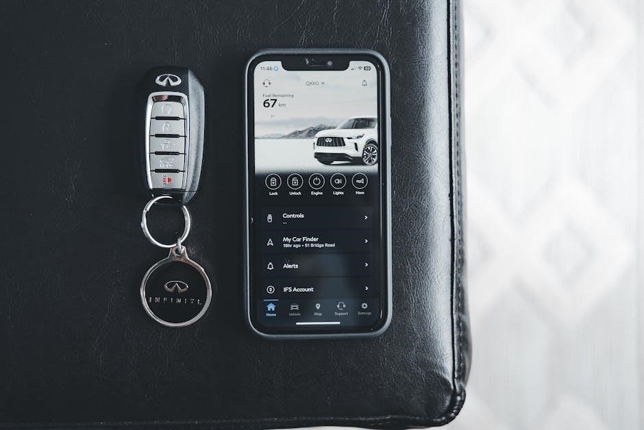
While the Infiniti QX60 primarily relies on the key fob for starting, and the manual key for emergency access, exploring alternative start methods is essential for comprehensive understanding. Some newer QX60 models may incorporate smartphone-based remote start systems through the Infiniti InTouch app, offering a convenient alternative to the physical fob.
However, these app-based systems typically require an active subscription and a properly configured account. They are not a direct replacement for the key fob or manual key, but rather a supplementary feature. Furthermore, certain aftermarket remote start systems can be installed by qualified technicians, providing another potential starting option.
It’s crucial to verify compatibility and ensure professional installation for any aftermarket system. Always prioritize security and adhere to Infiniti’s recommendations regarding vehicle modifications. The manual key start remains the most reliable fallback when all other methods are unavailable, ensuring you can regain control of your vehicle.
Resources for Key Replacement & Programming
Losing your Infiniti QX60 key fob or needing a replacement requires accessing reliable resources. Infiniti dealerships are the primary source for genuine key fobs and professional programming services, ensuring compatibility and security system integration. Expect to provide proof of ownership, such as vehicle registration and driver’s license.
Several reputable automotive locksmiths specialize in key fob replacement and programming for Infiniti vehicles. These locksmiths often offer faster service and potentially lower costs than dealerships, but verifying their credentials and experience is crucial. Online retailers sell aftermarket key fobs, but programming these fobs often requires specialized equipment and expertise.
Infiniti’s official website provides contact information for dealerships and customer support. Websites like KeylessRemote.com and others offer key fobs, but programming instructions may vary. Remember that improper programming can disable your vehicle’s security system, so professional assistance is often recommended.
QX60 Key System FAQs
Q: Can I drive my QX60 if my key fob battery is dead? A: Yes, utilizing the manual key function allows door unlocking and, with the correct procedure, engine starting. However, some features may be limited.
Q: What if my QX60 doesn’t recognize the key? A: Ensure the key fob battery isn’t depleted. Interference from other electronic devices can sometimes cause issues; try moving to a different location. If the problem persists, consult a dealership.
Q: Is it possible to program a new key fob myself? A: While some aftermarket options exist, Infiniti recommends professional programming at a dealership or by a qualified locksmith to ensure proper security integration.
Q: What security risks are associated with manual key use? A: While convenient, manual key use bypasses some security features. Be mindful of your surroundings and avoid leaving the key accessible in public areas.
Q: Where can I find the manual key inside the fob? A: Refer to the “Accessing the Manual Key from the Fob” section for detailed instructions on safely removing the physical key.